Identify 24° Tube Fittings
Identifying 24° Tube Fittings
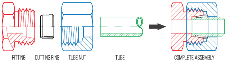
24° tube fittings, or ‘Bite-Type,’ are the most popular fitting globally and employ the most advanced tube fitting system in the world. This system is capable of withstanding high pressures and extreme vibration, thanks to the cutting ring design. The cutting ring is a ferrule that incorporates sharp cutting edges. When a nut is torqued onto the fitting, the base of the nut comes into contact with the cutting ring, wedging it into the 24° tapered throat of the fitting thereby cutting into and gripping the tube. Identify with caution, DIN fittings employ Metric threads and closely resemble other Metric fittings.
24° Throat Angle
The fitting itself incorporates a 24° tapered throat adjacent to the tube receptacle (where the tube ‘bottoms out’), which guides the wedging of the cutting ring while the nut provides torque. Proper attention must be given to the relevant installation instructions in order to achieve a properly sealed assembly. Refer to the assembly instructions for details.
Variations and Styles
There are numerous variations of cutting rings available, as well as mating styles incorporating swivel nuts, tube nipples and/or hose ends that replace the cutting ring in order to provide a seal. The latter versions do not require assembly by means of torquing the tube nut as the flare is already incorporated into the tube or hose. However, the 24° fitting and nut remain consistent throughout the varying styles.

Pressure Classes
This tube fitting system is commonly referred to as Bite-Type, DIN 2353, or ISO 8434-1. The 24° fitting, nut, and cutting ring comes in three different classes: LL for low pressure applications, L for medium pressure applications, and S for high pressure applications. For working pressures and compatible components, please refer to the ‘Component Compatibility Chart’ below:
|
PRESSURE
SERIES |
TUBE 0.0 |
METRIC THREAD
CALLOUT |
WORKING
PRESSURE (BAR)* |
TUBE NUT
PART # |
CUTTING RING
PART # |
TUBE PLUG
PART # |
TUBE CAP
PART # |
|---|---|---|---|---|---|---|---|
| LL | 4 mm | 8 mm X 1.0 | 100 | 5201LL-04 | 5202LL-04 | – | – |
| 6 mm | 10 mm X 1.0 | 100 | 5201LL-06 | 5202LL-06 | – | – | |
| 8 mm | 12 mm X 1.0 | 100 | 5201LL-08 | 5202LL-08 | – | – | |
| 10 mm | 14 mm X 1.0 | 100 | 5201LL-10 | 5202LL-10 | – | – | |
| 12 mm | 16 mm X 1.0 | 100 | 5201LL-12 | 5202LL-12 | – | – | |
| L | 6 mm | 12 mm x 1.5 | 315 | 5201L-06 | 5202-06 | 5203L-06 | 5204L-06 |
| 8 mm | 14 mm x 1.5 | 315 | 5201L-08 | 5202-08 | 5203L-08 | 5204L-08 | |
| 10 mm | 16 mm x 1.5 | 315 | 5201L-10 | 5202-10 | 5203L-10 | 5204L-10 | |
| 12 mm | 18 mm x 1.5 | 315 | 5201L-12 | 5202-12 | 5203L-12 | 5204L-12 | |
| 15 mm | 22 mm x 1.5 | 315 | 5201L-15 | 5202-15 | 5203L-15 | 5204L-15 | |
| 18 mm | 26 mm x 1.5 | 315 | 5201L-18 | 5202-18 | 5203L-18 | 5204L-18 | |
| 22 mm | 30 mm x 2.0 | 160 | 5201L-22 | 5202-22 | 5203L-22 | 5204L-22 | |
| 28 mm | 36 mm x 2.0 | 160 | 5201L-28 | 5202-28 | 5203L-28 | 5204L-28 | |
| 35 mm | 45 mm x 2.0 | 160 | 5201L-35 | 5202-35 | 5203L-35 | 5204L-35 | |
| 42 mm | 52 mm x 2.0 | 160 | 5201L-42 | 5202-42 | 5203L-42 | 5204L-42 | |
| S | 6 mm | 14 mm X 1.5 | 630 | 5201S-06 | 5202S-06 | 5203S-06 | 5204S-06 |
| 8 mm | 16 mm X 1.5 | 630 | 5201S-08 | 5202S-08 | 5203S-08 | 5204S-08 | |
| 10 mm | 18 mm X 1.5 | 630 | 5201S-10 | 5202S-10 | 5203S-10 | 5204S-10 | |
| 12 mm | 20 mm X 1.5 | 630 | 5201S-12 | 5202S-12 | 5203S-12 | 5204S-12 | |
| 14 mm | 22 mm X 1.5 | 630 | 5201S-14 | 5202S-14 | 5203S-14 | 5204S-14 | |
| 16 mm | 24 mm X 1.5 | 400 | 5201S-16 | 5202S-16 | 5203S-16 | 5204S-16 | |
| 20 mm | 30 mm X 2.0 | 400 | 5201S-20 | 5202S-20 | 5203S-20 | 5204S-20 | |
| 25 mm | 36 mm X 2.0 | 400 | 5201S-25 | 5202S-25 | 5203S-25 | 5204S-25 | |
| 30 mm | 42 mm X 2.0 | 400 | 5201S-30 | 5202S-30 | 5203S-30 | 5204S-30 | |
| 38 mm | 52 mm X 2.0 | 315 | 5201S-38 | 5202S-38 | 5203S-38 | 5204S-38 |
*1 BAR – 14.7 psi
Identifying 24° Metric Tube Fittings
The first step is to look for a size and series listed on the nut itself. It should list something like LL-08, 18-L, S20 or similar. Once identified, refer to the ‘Component Compatibility Chart’ above for information on relevant components such as cutting rings, plugs, and caps. Not all manufacturers list this information on the nut, so further steps might be required.
Determine Size & Series Manually

If no sizing information is available on the nut, the next step is to take a caliper reading of the outer diameter (O.D) of the tube or the inner diameter (I.D) of the tube receptacle inside the fitting. Be sure to set your calipers to millimeters (mm) as this is the unit of measurement all Metric tube fittings and the subsequent dash size system is based on. Note this measurement for later use.

The next step is to identify the thread size and pitch. To identify thread size on a metric thread, simply take a caliper reading of the outer diameter (O.D) of the threads. With metric threads, the O.D reading directly translates to thread size (i.e. an outer diameter reading of 22.05mm equates to a 22mm thread). To identify the thread pitch, there are two options: a) use a caliper to measure the distance between thread crests (in mm), or b) use a thread pitch gauge, which is recommended in order to avoid false identification. Thread pitches in the 24° DIN tube fitting class are 1.0mm, 1.5mm, or 2.0mm. The thread size and pitch are then combined to form the ‘thread callout’, which could be displayed as M22x1.5 or 22mm x 1.5, etc.

Compatibility: Fitting & Component
Lastly, compare the readings with the ‘Component Compatibility Chart’ in order to verify the size and series. For example, the thread O.D is 22mm, the thread pitch is 1.5mm, while the tube size measured is 15mm. Looking at the chart, a 15mm tube size with corresponding thread callout of M22x1.5 would indicate this assembly belongs to the L series for medium pressure, or more specifically as L15. From this chart one will find part numbers for compatible components such as tube nuts, cutting rings, as well as tube plugs and caps. Be sure to verify tube size as some thread sizes overlap between the pressure series i.e. an M14x1.5 thread could belong to the L or S series.
Assembling 24° DIN Tube Fittings
- The first step in assembly is to cut the tube to length, then de-burr and clean. Cut tubing with appropriate saw only.
- Next, pre-set the cutting ring by initiating the bite into the tube. There are two ways to complete the pre-set: either a) manually with a fitting or hardened pre-assembly fitting body, or b) with a hydraulic pre-set machine. Hydraulic pre-setting is recommended for assemblies with tube size greater than 18mm.
- Perform pre-set inspection to verify proper installation of cutting ring.
- Install the assembly.
Manual Pre-set Method
To manually pre-set the cutting ring you will need either the fitting or a hardened pre-assembly fitting body. Hardened pre-assembly bodies are recommended for higher volume jobs, or when using Stainless Steel tube or standpipe fittings.
- Lubricate threads of fitting and nut, 24° throat, and cutting ring.
- Place nut then cutting ring over tube, ensuring proper orientation.

- Thread nut onto fitting until finger tight. Press tube firmly into the tube receptacle of the fitting while doing so.
- Mark nut and tube position for reference with soap stone or marking pencil.
- Tighten nut so that it completes 1.5 turns (use markings as reference), while at the same time ensuring the tube is stationary and pressed firmly into the tube receptacle. Sudden resistance to torquing is a sign the cutting ring is in a desired position. Be sure to secure fitting with wrench while tightening the nut.

Hydraulic Pre-set Method
There are various hydraulic pre-set machines available with specific instructions for each. Please refer to your user’s manual for operating instructions.
Inspection
Remove the nut from fitting and pull back in order to inspect the cutting ring. The cutting ring should leave no visible gap between the first cutting surface and the tube, and the tube should have a visible bite edge in front of the cutting ring (looks like slightly raised material). If not, tighten in small increments (checking the result after each increment) to verify cutting ring is properly gripping the tube. It is possible for the ring to rotate around the tube, however this does not indicate an improper installation as long as all other factors are correct.

Install
Take the pre-set assembly and insert tube into the fitting’s tube receptacle firmly, then tighten nut with light wrenching until resistance felt. Once this has been achieved, tighten the nut another 30° or 1/12th of a turn. This is the equivalent of turning the nut from a state where the hex is flat relative to a fixed point (i.e. a table) to where the sharp edge of the hex is now facing that position. Be sure to use a second wrench to hold the fitting in place while torquing the nut.

Ordering DIN Tube Fittings from Hydraulics Direct
To order 24° DIN tube fittings from Hydraulics Direct it is important to understand the part number system. This system is typical of most manufacturers:
- The first four numbers indicates the part series i.e. 5000 is a male DIN union.
- The pressure class (LL, L, or S) is indicated at the end of the series number i.e 5000L, 5002S, 5063LL, etc.
- For instances where a DIN x DIN fitting does not have a jump size, only one dash size is displayed. For example, a 5000L-06 is a light duty L06 x L06 DIN union.
- The dash numbers indicate tube size when describing the DIN side of the fitting. From the last example, a 5000L-06 is an L06 indicating a M12x1.5 thread with 6mm tube receptacle; see the ‘Component Compatibility Chart’ in the How to Assemble 24° DIN Tube Fittings section for details on tube size & thread size relationship.
- For non-DIN threads such as NPT, BSPP, etc., the regular dash system is used i.e. -08 indicates 1/2”, -12 is 3/4”, etc. Hydraulics Direct usually displays dash sizes with tube or hose side first, then port side.
- To order a complete DIN assembly (including fitting, cutting ring, and nut) simply add a “C” to the end of the part number. For example, a complete L06 male DIN union assembly would be 5000L-06C, etc. Please note that all LL series (extra light duty) parts come complete. When a complete assembly is ordered from Hydraulics Direct, there is no need to identify components to go along with your assembly. Hydraulics Direct will complete the necessary steps to ensure you are provided with compatible components.